GDAL Geotransforms and World Files
The last post in this series considered how to write a geospatially aware file, in that case a Geotiff. In the example the projection and geotransform were read from a file and written into another file with no modification. That worked for the simple example, but isn’t necessarily the most common use case for that type of subroutine. Often you may want to adjust the data based on your analysis.
Most geospatial professionals are probably familiar with world files, or have at least run across them. They are a good way to georeference data that are not in a geospatially-aware format. While they are limited in their scope (they contain no projection information), if you want a quick and dirty way to georeference a file, they work well. You can always use your GIS to move your data into a map projection.
In the previous posts in this thread, a geospatial file was read and part of what was returned was the geotransform block. This block is defined as:
geotransform[0] = East/West location of Upper Left corner

geotransform[1] = X pixel size

geotransform[2] = X pixel rotation

geotransform[3] = North/South location of Upper Left corner

geotransform[4] = Y pixel rotation

geotransform[5] = Y pixel size
Many people may notice that these are the same values required for a world file, simply in a different order. On the surface, these seem like very reasonable parameters. There are no units provided, because the units will be the default units of whatever projection you plan to use. For example, if we are using a geographic coordinate system (EPSG:4326) then we would use decimal degrees or if, as in my case, we are using UTM Zone 11 North (EPSG:32611) we would use meters.
On the surface, the values look very simple. The location of one pixel (Upper Left corner), the pixel resolution and the rotation. In many cases, you will see references like “The rotations are normally/always set to zero”. This is true if your data are already oriented North up. If they are not, then the rotations are not zero and the pixel size is not the pixel size of a North-up image. I think this statement about the rotations stems from two reasons. First, most people are working with data that has already been projected and satisfy the North-up requirement to make the statement true. Secondly, I believe (though have not confirmed) that until recently a popular closed-source GIS program did not support world files or georeferencing of images that were not North-up oriented. Meaning if the rotation values were non-zero, they were ignored. It seems clear that could cause some problems.
Luckily, QGIS handles rotation values fine and that is what I generally use for validation of georeferenced images. The problem now is what do these values mean and how can they be calculated. I generally expect rotations to be in angular units, but it is not. As you can see from the image below (courtesy of Wikipedia) all values in the geotransform block are in your projection units.
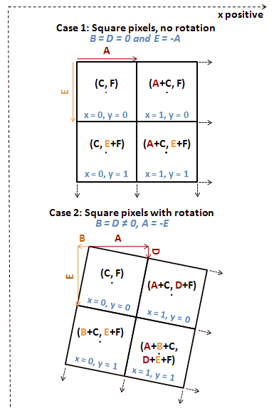
When we rotate an image, the pixel resolution and rotation values vary as their component mapped into a cartesian grid. If you define your rotation angle as varying from true North, then this is your aircraft true bearing and these component values become:
geotransform[1] = X Pixel Size * cos(Bearing Angle)

geotransform[2] = -1*X Pixel Size * sin(Bearing Angle)

geotransform[4] = Y Pixel Size * sin(Bearing Angle)

geotransform[5] = Y Pixel Size * cos(Bearing Angle)
Again, where the Bearing angle is referenced to true, not magnetic, North and the X/Y Pixel Resolution refer to the native, unrotated pixel size. One quick note here is that the above definitions assume your X and Y resolution have the customary notation of X resolution being positive and Y resolution being negative. If you have positive X and Y resolutions, then elements [4] and [5] should be multiplied by -1.
Given these reasonably simple definitions it is quite easy to generate geotransforms or world files for any data you may have. Additionally, the geotransform block can be used to make small adjustments to your data. Many years ago, I created a simple routine that coregisters two images. In this routine, after the translational offsets of the images are calculated, I simply modify the geotransform block of one of images to correct for the offset.
Geotransforms are simple in form, and once you understand them, they can be a powerful tool in your toolbox of skills for working with geospatial data. Thank you for reading and if you have questions or comments, I invite you to leave them in the comment block. This is a new series of posts and I am wondering if readers are finding them useful.
Next post in this thread will discuss how to work with map projection information in GDAL and python.
I think the calculation for geotransform[2] should have Y Pixel Size instead of X Pixel Size. Similarly geotransform[4] would have X Pixel Size instead of Y Pixel Size. I.e. to calculate coordinates (x, y) for row j and column i, the equation is:
x = ulx + i*pxl_width*cos(theta) – j*pxl_height*sin(theta)
y = ulr – i*pxl_width*sin(theta) – j*pxl_height*cos(theta)
so
geotransform[1] = pxl_width*cos(theta)
geotransform[2] = -pxl_height*sin(theta)
geotransform[4] = -pxl_width*sin(theta)
geotransform[5] = -pxl_height*cos(theta)
(where pxl_width and pxl_height are positive)